Thursday, May 19, 2016

Work Night 5.18.16

Work Night
Date: 5.18.16
Location: Logan HS
Time: 4:00-7:30 PM
Goal: Test out the main drive interface.
Students: Grant and Killian

We really have been working on the software and hardware solution for the main drive (MD) interface. Friday, Grant spent about 3 hours on Friday looking over the software trying to find a solution to the PWM signal problem we have. Not much luck looking at Pixhawk forums for Rover configuration details and 3DR does not have technical support (call in) for converting your Pixhawk to a rover. We need a hardware solution.

The MD interface tested out well on the Oscope after a few bugs were worked out. We now can adjust to approximately a 5 V  high and we can adjust to a low. This process took a couple of hours to work out and that is just for the MD. Then we have to look at a solution for the steering.

We found an Arduino option that has an Arduino filter and convert the signal to a binary output which we can use. Much easier than hardware if we can configure the output signal. We will work on that over the next couple of days to see if it works.

We wanted to get more of the components onto the vehicle but we were unable to because of the software MD problem we were having. Sometimes it seems like we take two steps forward and one back but that is troubleshooting.

Next week we will have more time to work on the vehicle and hopefully get everything on the frame and wired.


More components added to frame

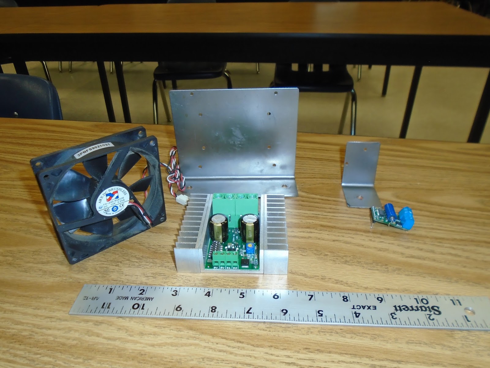
Our main drive interface

Testing the MD interface with Pixhawk

Testing steering and main drive interface

Notes on main drive interface

Test board is getting congested with added components

Thursday, May 12, 2016

Work Night 5.11.16

Work Night
Date: 5.11.16
Location: Logan High School
Time: 4:15-7:15 PM
Goal: Connect controller and work on output signals and wire in motor controls.
Students: Oscar, Grant (Max came in to help also) Additionally, James, Issac, Owen and John worked on this during DE class.

We are expanding our work nights to days also so we probably put in about 4 hours working on various aspects of the AV during the school day.

Our main priority is to get the Pixhawk controller output signal programmed in a way that the PWM signal is useful to us. Right now it defaults to about a 10% power on immediately upon arming the controller. That we do not want as the motor would start turning immediately. We have to find a way to change the output of the signal to match a traditional throttle output. On the plus side, we were able to hook up an O-Scope and see that we are getting about a 3V PWM signal when the throttle is full speed. We had problems earlier arming the Pixhawk as many of the defaults had to be changed and the documentation for converting the Pixhawk (designed to be used on drone aircraft) to a rover is very in depth. Our goal in the next couple of days is to work on getting that signal tuned in.

Wiring is going well and we only have to solder two small circuits for the the output logic with the optoisolator circuits. Our first real motor test went well. It was good to see a motor actually turn after all the wiring we did.

We will plan another work night next week.
Our relay box getting wired.

Testing our Pixhawk controller.

Enclosing our circuitry to protect it.

Car frame has been painted and is ready for components.

Getting a value on our PWM signal using an O-Scope.

Soldering a connection on the relay box.

Motor Test #1 using a small motor just for testing purposes.

Friday, May 6, 2016

Work Night 5.6.16

Work Night
Date:5.5.16
Location: Logan HS
Time: 4:15-8:45 PM
Students: Joey and Grant (Max also stopped back in to help)
Goal: Get the main drive (relays, switches, etc..) wired an tested.

We were able to get most of the switches and relays wired in along with our main motor drivers. We did a quick test to see if the motor driver was outputing to the motor using a power resistor to simulate the motor. We did get a current draw so we know that works. We are having a problem with one of the momentary switches which turns on the main drive. We needed another hour of troubleshooting so we will have to work on that next time we meet. Once we have this tested, we will begin working on the RF side for our controller inputs.

Joey finding the correct resistor.

Our relay box partially wired.

Our test bed with all the wiring and components on it. We still have to add a few things.

We found we need a lot of table space for this project.

Thursday, May 5, 2016

Work Night 5.4.16

Work Night 

Date: 5.4.16
Location: Logan High School
Time: 4:15 PM-8:00 PM
Goal: Place boxes, solder circuits, and wire up to the motor drivers.
Students: Oscar, Grant, Killian and Isaac
Also former student..Max Sexauer and Dave Foye, Engineering Consultant

We had a great work night and got many things accomplished. The main focus was to begin to getting everything wired based on our schematic. We also had to make boxes for relays and our other soldered components to protect them. The front steering circuit was tested with the linear actuator. After some troubleshooting it was determined that the terminal block we were using had some rusted connections and was not conducting. After working around that, the linear actuator tested successfully from our motor driver.

Components for the suppression network for our main motor were soldered direct to circuit board. We plan to work on the AV again tomorrow night to wire in the main drive motor and motor driver and test it.

Students work on various fabrication assignments

Testing the linear actuator.

Soldering connections and wiring circuits.

Testing parts of the suppression network.

Tristan spraying a coat of primer on the frame in our spray booth.
t


Saturday, April 30, 2016

Work Day Saturday, 4.30.16

Work Day Saturday, 4.30.16
Location: Logan HS Tech Ed Dept.
Time: 10:30 AM-12:30 PM
Goal: Install case fan on main motor driver and mount steering driver on bracket.

We have been spending a lot of time at Ace Hardware looking for various small fasteners to attach motor drivers and fans to mounts. The challenge was to mount a 12 V case fan from a computer to the bracket we made for the main motor driver. It had to be set at an adjustable height because we are unsure what temps the driver will throw off. Our front steering driver is small so we were able to use a grommet to space the driver off the metal bracket so we did not create a fault.

The optoisolator input to the steering motor driver has been breadboarded also.

Looking forward to this week because we will have two work nights and we feel we can wire most of the electronic components and then begin bench testing to troubleshoot everything.

Optoisolator input to the steering motor driver.

Completed main motor driver with heat synch and fan.

Steering motor driver mounted on bracket we made.

Thursday, April 28, 2016

AV Work Night 4.28.16

AV Work Night 4.28.16

Time: 4:30-7:30 PM
Location: Logan HS
Goal: To build mounts for both motor drivers and begin to wire in the main circuit breaker.

We have our wiring schematic to the point where we can begin to wire up the motor drivers. Changes will still have to be adapted as bench testing progresses. Tonight we wanted to get brackets machined to mount the two motor drivers. It was decided to mount them in a vertical manner to maximize cooling. On the main drive motor we scavenged a 12 V fan out of a computer tower to place on top of that motor driver. The specs say it is not needed, but better to be safe than sorry. If we burn out that motor driver it is too costly to replace. The motor driver for the linear actuator is smaller and will run a bit cooler.

We also wanted to begin running some wire for the main breaker and battery. Nothing is terminated in the pictures, we just want to get lengths and crimp on ring terminals.

On the next work night we will begin to wire up the controller in suppressor logic.

This is what we started with for fabricating the mounts.

Finished mounts before painting.

Nothing terminated in the breaker box yet, just getting wire lengths down so we can begin crimping and soldering connectors.

Electrical System & Wiring Schematic Drafts 4.25.16

Electrical System & Wiring Schematic Drafts 4.25.16

Working with Electrical Engineer Dave Foye, we have the first draft of the wiring schematic for our drive train and steering control and we anticipate changes after bench testing occurs. Careful consideration had to go into the design of the suppression system.


First draft of wiring schematic
Work continues on the vehicle. We are getting closer to paint ready.


Still need to add chain guard, support structure and linear actuator, but Mr. Pitz and Tristan have it outfitted for our solar panel.