Saturday, April 30, 2016

Work Day Saturday, 4.30.16

Work Day Saturday, 4.30.16
Location: Logan HS Tech Ed Dept.
Time: 10:30 AM-12:30 PM
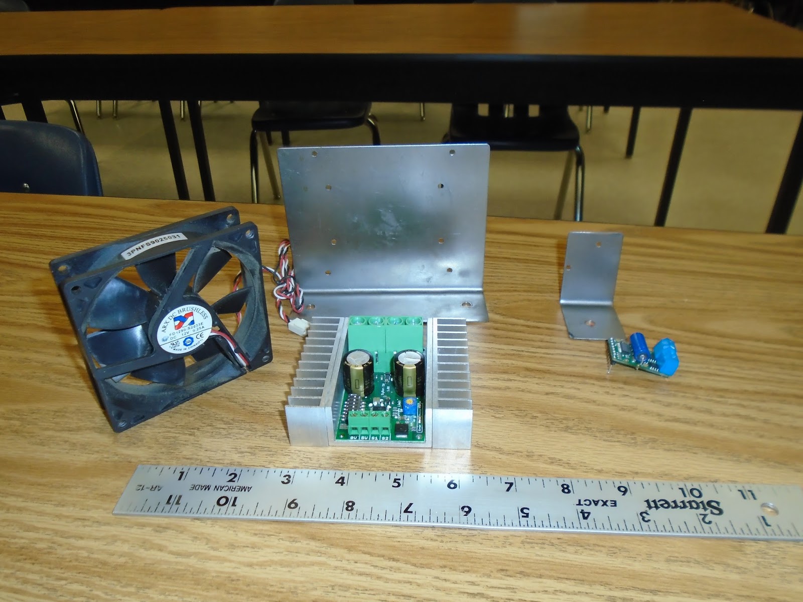
Goal: Install case fan on main motor driver and mount steering driver on bracket.

We have been spending a lot of time at Ace Hardware looking for various small fasteners to attach motor drivers and fans to mounts. The challenge was to mount a 12 V case fan from a computer to the bracket we made for the main motor driver. It had to be set at an adjustable height because we are unsure what temps the driver will throw off. Our front steering driver is small so we were able to use a grommet to space the driver off the metal bracket so we did not create a fault.

The optoisolator input to the steering motor driver has been breadboarded also.

Looking forward to this week because we will have two work nights and we feel we can wire most of the electronic components and then begin bench testing to troubleshoot everything.

Optoisolator input to the steering motor driver.

Completed main motor driver with heat synch and fan.

Steering motor driver mounted on bracket we made.

Thursday, April 28, 2016

AV Work Night 4.28.16

AV Work Night 4.28.16

Time: 4:30-7:30 PM
Location: Logan HS
Goal: To build mounts for both motor drivers and begin to wire in the main circuit breaker.

We have our wiring schematic to the point where we can begin to wire up the motor drivers. Changes will still have to be adapted as bench testing progresses. Tonight we wanted to get brackets machined to mount the two motor drivers. It was decided to mount them in a vertical manner to maximize cooling. On the main drive motor we scavenged a 12 V fan out of a computer tower to place on top of that motor driver. The specs say it is not needed, but better to be safe than sorry. If we burn out that motor driver it is too costly to replace. The motor driver for the linear actuator is smaller and will run a bit cooler.

We also wanted to begin running some wire for the main breaker and battery. Nothing is terminated in the pictures, we just want to get lengths and crimp on ring terminals.

On the next work night we will begin to wire up the controller in suppressor logic.

This is what we started with for fabricating the mounts.

Finished mounts before painting.

Nothing terminated in the breaker box yet, just getting wire lengths down so we can begin crimping and soldering connectors.

Electrical System & Wiring Schematic Drafts 4.25.16

Electrical System & Wiring Schematic Drafts 4.25.16

Working with Electrical Engineer Dave Foye, we have the first draft of the wiring schematic for our drive train and steering control and we anticipate changes after bench testing occurs. Careful consideration had to go into the design of the suppression system.


First draft of wiring schematic
Work continues on the vehicle. We are getting closer to paint ready.


Still need to add chain guard, support structure and linear actuator, but Mr. Pitz and Tristan have it outfitted for our solar panel.


Friday, April 22, 2016

AV Work Night 4.21.16

AV Work Night 
Date: 4.21.16
Students: Grant and Clare
Time: 4:30-7:10 PM
Location: Logan HS
Goal: Solder and wire connections to motor and begin experimenting with the optoisolator relay circuit.

We needed to upgrade the crimped wire connections from motor to switch, fuse and other components with soldered connections. Need to purchase a soldering gun as 12 gauge wire is too big for our small soldering irons. Clare was working hard on those connections.


We needed to start experimenting with our relays to see if we needed to use a relay or a motor driver. Grant worked on soldering up a relay to test on our motor with the optoisolator.


After we wired the test circuit together we took it into the shop to try it on the vehicle. The relay would turn the motor on, but when we varied the current through the opotisolator we could not get the motor to stop. We felt we had the relay wired in wrong as we had a +5 V on our optoisolator and it seemed to be isolating our controller as it should do. 

Grant and Clare working on the relay wire.

More work needs to be done on if a relay or a motor driver would be our best option. Our next test will feature a 18V motor driver to see if we can get a more positive result with output to our motor.


Friday, April 15, 2016

AV Work Night 4.14.16

AV Work Night
Date: 4.14.16
Students: Grant and Owen
Time: 4:00-7:30 PM
Location: Logan HS
Goal: Program and calibrate controller for the AV.

Work progresses on the Autonomous Vehicle. The main goal tonight was to work on configuring the controller for our GPS system. We also started to build the control pod which will allow us place all of our motor drivers, relays, etc... in a central location. This will be moved to and from the vehicle when programming or testing is needed to be done.

We want to make as much of the wiring and connections to various components transparent. This means we don't want to cover the frame with a sheet metal body. We want students to see how the wires and components are hooked together so they can physically trace current paths. In doing so, even after the project is completed the AV continues to be an educational tool in the future.

Grant working on programming the controller. Also pictured is the 30 W solar panel we will incorporate in the charging system.

This is the start of our control pod. It is being mounted on acrylic glass for to allow for transparency. A small breadboard and 12 V relay are being mounted next to the mount for our controller and GPS which will be placed above on the mast.

Welding is coming along on the vehicle frame.The front wheels are mounted and students are getting ready to place the linear actuator  to direct the steering on the frame. A big thanks to Mr. Pitz and his student assistant Tristan for their work on this.


Friday, April 8, 2016

Fabrication of Autonomous Vehicle Frame Begins

Fabrication of Autonomous Vehicle  Frame Begins

Students started to tack weld the frame of the Autonomous Vehicle today. We based the measurements off of the mock up test bed we are using for designing the electronics.

In the picture below you see Tristan tack welding the tube stock which forms the base of the frame.