Tuesday, May 31, 2016

AV Work Day

AV Work Day
Date:5.31.16
Time: 7:30 AM-1:30 PM
Location: Logan HS
Students: Clare, Isaac, Zach, and Oscar
Goal: Test out interfaces and solder all connections together if testing is positive.

A lot of little time consuming work today testing out the interfaces and soldering connections together that were previously mounted and wired with terminal strips. The good news is the tests working on the vehicle and our steering and main drive work. We had a limit switch (or lack there of) problem with our steering mechanism. The linear actuator works well, but when it moves to full extension, it drives our control arm into the frame. We have to adjust that or add limit switches to the design. The actuator is always trying to sense "center point" so we get some back and forth motion with the actuator when the vehicle is going straight.

Students came in on their day off to work on this. We have about 7-8 wires to solder and we should be ready for a test run on the blacktop tomorrow.

Zach and Oscar working on some connections.

Clare and Isaac soldering.
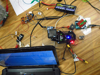
First test of the main drive interface with the entire system together.


AV Work Day 5.27.16 and 5.26.16

AV Work Day
Date:  5.27.16 and 5.26.16
Time: 6:30 AM-8:00 AM and 8:30 AM-Noon
Location: Logan HS
Goal: Finish the majority of the wiring except for interface connections.

All the boxes are now mounted to the vehicle chassis. It took some time to drill holes into the metal frame and then align the boxes. Our controllers and shielding material are now placed on the vehicle and secured with velcro so they can be removed easily to program. Wires had to be resoldered to extend them to appropriate control box.  We still have to connect to motor drivers and then test those connections. Hoping we are ready for a test drive on Tuesday when we are back from the Memorial Day Holiday.

Side view of vehicle with controller mounted in place.

Front view of AV with linear actuator in place.

Identifying the wires sources.

Top view of the front steering components.

Thursday, May 26, 2016

AV Work Day 5.25.16


AV Work Day
Date: 5.25.16
Location: Logan HS
Time: 9:44-11:15 AM and 4:00-7:30 PM
Students: DE Class and then after school Oscar and Grant
Goal: Test forward and reverse on main motor drive along with front steering control.

This was a breakthrough day for us. We were able to configure the controller and the motor driver to move the linear actuator for steering. We also tested forward and reverse on the main drive. It has been about a month and a half of bench testing.  Finally being able to take off components we have built and start to mount them on the actual vehicle was a good feeling for the kids.

We had a problem with one of the computer cables we scavenged from some old PC’s. One of the pinouts we were using for direction on the front steering must have had a broken wire in it because our steering was not responding the way we would have liked. Troubleshooting took quite a while to detect it.

After the bench test, we moved all the components to the vehicle. Grant made another box for the steering interface and Oscar remounted the main motor driver which needed to be moved so we could access the chain guard.

Our next goal is to mount all components and then do a systems test next Tuesday. Still looking at an end of school completion date.


Grant and Oscar testing the steering system.

I know...it is just a piece of plywood but this was what we used for bench testing. All the components have been removed and assembled onto the vehicle so it is good to see it blank.
Rear motor drive test with a test motor wired up.


Components being assembled on vehicle.

Grant making a connection box for a component.

Som students soldering the wire connectors to our controller. They need to be 7 feet long so we can reach the different motor drivers on the vehicle.

Test video of linear actuator being tested for steering.

Monday, May 23, 2016

Work Day 5.23.16

Work Day on AV

Date: 5.23.16
Time: 9:35-11:05 AM
Location: Logan HS
Students: Clare, Theo, Isaac, Zach, Michael and Oscar
Goal: Get the main motor drive online so it can be controlled by transmitter. Also, fabricate shielding for the controller and and work on our wireless Live View System.


We took the class period to work on the AV. The good news is the main drive is working and paired with our transmitter so it can now be controlled. We also took some copper PCB board we are using for shielding and cut out holes for velcro strips to secure it.

We are getting closer all the time. Today was a big day because the main drive is now functional. Now for the steering. We have the hardware in place except for a little bit of wiring. The software has to be configured for a left turn (we believe we have the right turn down). If that works we are ready to test on the vehicle.

Looking toward Wednesday when we hope to finish up with our steering test and then move all the components onto the vehicle for final wiring and systems test.


Students working with Dave Foye on main drive interface.

Theo cutting out and fabricating shielding materials.

Main drive interface


Short video showing the transmitter controlling our test drive motor.

Thursday, May 19, 2016

Work Night 5.18.16

Work Night
Date: 5.18.16
Location: Logan HS
Time: 4:00-7:30 PM
Goal: Test out the main drive interface.
Students: Grant and Killian

We really have been working on the software and hardware solution for the main drive (MD) interface. Friday, Grant spent about 3 hours on Friday looking over the software trying to find a solution to the PWM signal problem we have. Not much luck looking at Pixhawk forums for Rover configuration details and 3DR does not have technical support (call in) for converting your Pixhawk to a rover. We need a hardware solution.

The MD interface tested out well on the Oscope after a few bugs were worked out. We now can adjust to approximately a 5 V  high and we can adjust to a low. This process took a couple of hours to work out and that is just for the MD. Then we have to look at a solution for the steering.

We found an Arduino option that has an Arduino filter and convert the signal to a binary output which we can use. Much easier than hardware if we can configure the output signal. We will work on that over the next couple of days to see if it works.

We wanted to get more of the components onto the vehicle but we were unable to because of the software MD problem we were having. Sometimes it seems like we take two steps forward and one back but that is troubleshooting.

Next week we will have more time to work on the vehicle and hopefully get everything on the frame and wired.


More components added to frame

Our main drive interface

Testing the MD interface with Pixhawk

Testing steering and main drive interface

Notes on main drive interface

Test board is getting congested with added components

Thursday, May 12, 2016

Work Night 5.11.16

Work Night
Date: 5.11.16
Location: Logan High School
Time: 4:15-7:15 PM
Goal: Connect controller and work on output signals and wire in motor controls.
Students: Oscar, Grant (Max came in to help also) Additionally, James, Issac, Owen and John worked on this during DE class.

We are expanding our work nights to days also so we probably put in about 4 hours working on various aspects of the AV during the school day.

Our main priority is to get the Pixhawk controller output signal programmed in a way that the PWM signal is useful to us. Right now it defaults to about a 10% power on immediately upon arming the controller. That we do not want as the motor would start turning immediately. We have to find a way to change the output of the signal to match a traditional throttle output. On the plus side, we were able to hook up an O-Scope and see that we are getting about a 3V PWM signal when the throttle is full speed. We had problems earlier arming the Pixhawk as many of the defaults had to be changed and the documentation for converting the Pixhawk (designed to be used on drone aircraft) to a rover is very in depth. Our goal in the next couple of days is to work on getting that signal tuned in.

Wiring is going well and we only have to solder two small circuits for the the output logic with the optoisolator circuits. Our first real motor test went well. It was good to see a motor actually turn after all the wiring we did.

We will plan another work night next week.
Our relay box getting wired.

Testing our Pixhawk controller.

Enclosing our circuitry to protect it.

Car frame has been painted and is ready for components.

Getting a value on our PWM signal using an O-Scope.

Soldering a connection on the relay box.

Motor Test #1 using a small motor just for testing purposes.

Friday, May 6, 2016

Work Night 5.6.16

Work Night
Date:5.5.16
Location: Logan HS
Time: 4:15-8:45 PM
Students: Joey and Grant (Max also stopped back in to help)
Goal: Get the main drive (relays, switches, etc..) wired an tested.

We were able to get most of the switches and relays wired in along with our main motor drivers. We did a quick test to see if the motor driver was outputing to the motor using a power resistor to simulate the motor. We did get a current draw so we know that works. We are having a problem with one of the momentary switches which turns on the main drive. We needed another hour of troubleshooting so we will have to work on that next time we meet. Once we have this tested, we will begin working on the RF side for our controller inputs.

Joey finding the correct resistor.

Our relay box partially wired.

Our test bed with all the wiring and components on it. We still have to add a few things.

We found we need a lot of table space for this project.

Thursday, May 5, 2016

Work Night 5.4.16

Work Night 

Date: 5.4.16
Location: Logan High School
Time: 4:15 PM-8:00 PM
Goal: Place boxes, solder circuits, and wire up to the motor drivers.
Students: Oscar, Grant, Killian and Isaac
Also former student..Max Sexauer and Dave Foye, Engineering Consultant

We had a great work night and got many things accomplished. The main focus was to begin to getting everything wired based on our schematic. We also had to make boxes for relays and our other soldered components to protect them. The front steering circuit was tested with the linear actuator. After some troubleshooting it was determined that the terminal block we were using had some rusted connections and was not conducting. After working around that, the linear actuator tested successfully from our motor driver.

Components for the suppression network for our main motor were soldered direct to circuit board. We plan to work on the AV again tomorrow night to wire in the main drive motor and motor driver and test it.

Students work on various fabrication assignments

Testing the linear actuator.

Soldering connections and wiring circuits.

Testing parts of the suppression network.

Tristan spraying a coat of primer on the frame in our spray booth.
t